 |
|
 |
Setting up and determining Parameters for Orbital Tube Welding
How to proceed when specs are not available
By Bernard Mannion and Jack Heinzman III
Orbital welding was first used in the 1960s in the aerospace industry. By the early 1980s, it became practical for many industries, when combination power supply/control systems were developed that operated from 110 volts alternating current (VAC) and were physically small enough to be carried around construction sites for multiple in-place welds.
Currently, typical industries using orbital welding include aerospace; food, dairy, and beverage; nuclear; offshore; pharmaceutical; and semiconductor. Other applications include boiler tubing and tube and pipe fittings, valves, and regulators.
Today's orbital welding systems offer computer controls that store a variety of welding parameters that can be called up as needed. In effect, the skills of a certified welder are built into the system, allowing it to produce consistent welds and leaving less room for error or defects.
 |
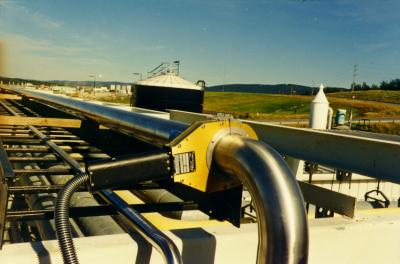
| Figure 1 Standard enclosed orbital weld heads can be used to weld tube sizes up to 6 inches and wall thicknesses up to 0.154 inch. |
In the orbital welding process, tubes and pipes are clamped in place, and an orbital weld head rotates an electrode and electric arc around the weld joint to make the weld (see Figure 1). An orbital welding system consists of this weld head and a power supply.
Orbital weld heads come in enclosed and open styles and provide an inert atmosphere chamber that surrounds the weld joint. Standard enclosed orbital weld heads are practical for welding tube sizes from 1/16 to 6 inches (1.6 to 162 millimeters) with wall thicknesses of up to 0.154 inch (3.9 millimeters). Large diameters and wall thicknesses can be accommodated with open-style weld heads.
The power supply/control system supplies and controls the welding parameters according to the specific weld program created or recalled from memory. The power supply provides the control parameters, the arc welding current, and the power to drive the motor in the weld head, and it switches the shield gases on and off as necessary.
For orbital welding in many precision or high-purity applications, the base material, tube diameter, weld joint and part fit-up requirement, shield gas type and purity, arc length, tungsten electrode material, electrode tip geometry, and electrode grind surface condition may already be written into a specification covering the application.
Each orbital welding equipment supplier differs slightly in recommended welding practices and procedures. Where possible, the recommendations of the supplier should be followed, especially in areas that pertain to warranties.
This article presents guidelines for applications that have no specifications and for which the welding engineer must create the welding setup and derive the welding parameters.
Physics of the GTAW Process
Orbital welding uses the gas tungsten arc welding (GTAW) process as the source of the electric arc that melts the base material and forms the weld. In the GTAW process, an electric arc in established between a tungsten electrode and the part to be welded.
To start the arc, a high-voltage signal (usually 3.5 to 7 kilovolts) is used to break down (ionize) the insulating properties of the shield gas and make it electrically conductive to pass through a tiny amount of current. A capacitor dumps current into this electrical path, which reduces the arc voltage to a level at which the power supply can then supply current for the arc.
The power supply responds to the demand and provides weld current to keep the arc established. The metal to be welded is melted by the intense heat of the arc and fuses together.
Material Weldability
The material selected varies according to the application and environment the tubing must survive. The mechanical, thermal, stability, and corrosion resistance requirements of the application dictate the material chosen. For complex applications, a significant amount of testing is necessary to ensure the long-term suitability of the chosen material from a functionality and cost standpoint.
In general, the most commonly used 300 series stainless steels have a high degree of weldability, with the exception of 303/303SE, which contain additives for ease of machining. The 400 series stainless steels are often weldable but may require post weld treatment.
Potential differences of material heats must be accommodated. Each heat batch number will have minor differences in the concentration of alloying and trace elements. These trace elements can vary the conductivity and melting characteristics of the overall material. When a change in heat number is made, a weld test coupon should be made for the new heat. Changes in amperage may be required to return the weld to its original profile.
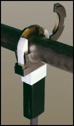
Certain elements of the material must be held to close tolerances. Minor deviations in elements such as sulfur can vary the fluid flow in the weld pool, completely changing the weld profile and potentially causing arc wander (see Figure 2).
 |
| Figure 2 Minor changes in sulfur content can change weld pool flow characteristics. |
Weld Joint Fit-up
Weld joint fit-up depends on the weld specification requirements for tube straightness, weld concavity, reinforcement, and drop-through. If no specification exists, the molten material must flow and compensate for tube mismatch and any gap in the weld joint.
Wall thickness should be repeatable at the weld joint from part to part. Differences in tube diameter or out-of-roundness cause weld joint mismatch and arc gap variations from one welding setup to another. In addition, tube ends must be square and flat, and both the inside diameter (ID) and outside diameter (OD) should be burr-free with no chamfer. In general, the following rules apply regarding mismatch and gaps:
1. Any gap should be less than 5 percent of the wall thickness. It is possible to perform orbital welding with gaps of 10 percent of wall thickness or greater, but the quality of the weld suffers, and repeatability becomes challenging.
2. Wall thickness variations at the weld zone should be ±5 percent of nominal wall thickness. Again the laws of physics can sometimes allow welding with a mismatch of up to 25 percent of wall thickness, but weld quality and repeatability are compromised.
3. Alignment mismatch (high-low) can be avoided by using engineering stands and clamps to align the two tubes to be welded. This system also removes the mechanical requirement of aligning the tubes from the orbital weld head.
Shield gases
An inert gas is required on the tube OD and ID during welding to prevent the molten material from combining with the oxygen in the ambient atmosphere. The objective of the welder should be to create a weld that has zero heat tint at the weld zone.
Argon is the most commonly used shield gas (for the OD) and purge gas (for the ID). Helium is often used for welding on copper material. Mixed gases such as 98 percent argon/2 percent hydrogen, 95 percent argon/5 percent hydrogen, 90 percent argon/10 percent hydrogen, 75 percent helium/25 percent argon are often used to create the optimal balance of arc starting, arc stability, final weld cleanliness, molten puddle fluidity, and weld penetration.
Mixtures of 95 percent argon/5 percent hydrogen are incompatible with carbon steels and some exotic alloys and can cause hydrogen embrittlement in the weld. To simplify matters and reduce shield gas cost, 100 percent argon gas is often used.
Gas purity is dictated by the application. For high-purity situations in which the concern for microcontamination is paramount, such as semiconductor and pharmaceutical applications, the shield and purge gases must minimize the heat tint that could otherwise be undesirable. In these applications, ultrahigh-purity gas or gas with at local purifier is used. For noncritical applications, commercial-grade argon gas may be acceptable.
Tungsten Electrodes
The tungsten welding electrode--the source of the welding arc--is one of the most important elements of the welding system that is commonly ignored by welding system users. While no one would refute the importance of the ignition device on an automobile air bag, the rip cord for a parachute, or quality tires for automobiles, the importance of tungsten electrodes for quality welding is often overlooked.
The objective for the choice of tungsten parameters is to balance the benefits of a clean arc start with reduced arc wander with good weld penetration and a satisfactory electrode life.
Electrode Materials. For quire some time, tungsten manufacturers have added an oxide to pure tungsten to improve the arc starting characteristics and longevity of pure tungsten electrodes. In the orbital welding industry, the most commonly used electrode materials are 2 percent thoriated tungsten and 2 percent ceriated tungsten. While both types have their own advantages and drawbacks, it is always best to follow the advice of the orbital welding manufacturer.
Electrode Tip Geometry. Given the ever-increasing weld quality requirements of the final weld, more companies are looking for ways to ensure that their weld quality is up to par. The shape and quality of the tungsten electrode tip are finally being recognized as vital process variables.
Welders should follow the equipment suppliers' suggested procedures and dimensions first because they have usually performed a significant amount of qualifying and troubleshooting work to optimize electrode preparation for their equipment. However, when these specifications do not exist or the welder or engineer would like to change those settings to possible improve and optimize welding the following guidelines apply:
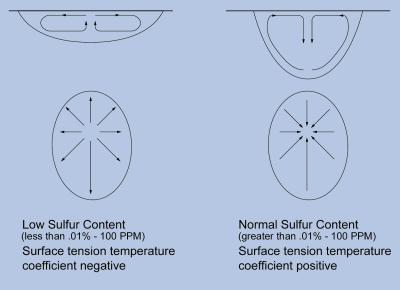
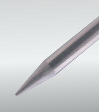
1. Electrode taper. This is usually called out in degrees of included angle (usually anywhere between 14 and 60 degrees). Figure 3 illustrates that characteristics of both sharp and blunt tapers. Figure 4 demonstrates how taper selection affects the size of the weld bead and the amount of penetration by showing a typical representation of the arc shape and resultant weld profile for different tapers.
| Sharper Electrode | Blunter Electrode |
| Easy arc starting | Usually harder to start |
| Handles less amperage | Handles more amperage |
| Wider arc shape | Narrower arc shape |
| Good arc stability | More chance of arc wander |
| Less weld penetration | More weld penetration |
| Shorter electrode life | Longer electrode life |
| Figure 3 This table compares the characteristics of both sharper and blunter electrode tapers. |
 |
| Figure 4 This drawing shows typical representations of the arc shape and resultant weld profile for various electrode tapers. |
2. Electrode tip diameter. Grinding an electrode to a point is sometimes desirable for certain applications, especially if arc starting is difficult or short-duration welds on small parts are performed. However, in most cases, the welder should leave a flat spot or tip diameter at the end of the electrode. This reduces erosion at the thin part of a point and reduces the possibility of the tip falling into the weld. Large and small tip diameters offer the trade-offs shown in Figure 5.
| Smaler Tip | Larger Tip |
| Easy arc starting | Usually harder to start |
| Good arc stability | More chance of arc wander |
| Less weld penetration | More weld penetration |
| Shorter electrode life | Longer electrode life |
| Figure 5 Depending on the welding application, different-sized tips may be required. |
Electrode Grinders. A dedicated commercial electrode grinder can be used to provide electrode tip quality and consistency.
In addition, a dedicated electrode grinder helps to ensure that the welding electrodes will not become contaminated by residue or material left on a standard shop grinder wheel.
 |
| Figure 6 Using preground electrodes ensures that the electrode material quality, tip geometry, and ground electrode surface input to the welding process is constant. |
Preground Electrodes. Because each operator grinding the electrodes has a slightly different touch, resulting in variable results, some manufacturers purchase electrodes pre-ground (see Figure 6). This option helps to ensure that the electrode material quality, tip geometry, and ground electrode surface input to the welding system is constant. Electrode charts or elctrode suppliers can provide the electrode diameter and tip geometry that are most suitable for particular welding application. Using an electrode grinder or preground electrodes (preferred):
1. Improves arc starting, increase arc stability, and make weld penetration more consistent.
2. Increases electrode life before electrode wear or contamination.
3. Reduces tungsten shedding, which minimizes the possibility or tungsten inclusions in the weld.
Weld Parameter Development
Many welding equipment suppliers offer a series of precalculated weld programs for a variety of tube diameters, wall thicknesses, and materials. Welders should always follow an equipment supplier's suggested procedures first. However, it is impossible for the equipment suppliers to have welding procedures for every welding application, and there will always be a trade-off in maximum possible weld speed versus weld quality and repeatability.
| Given the ever-increasing weld quality requirements of the final weld, more companies are looking for ways to ensure that their weld quality is up to par. |
When weld parameter specifications do not exist or welders or engineers would like to change those settings possibly to improve their welding, the following guidelines should be followed for modifying the welding parameters for a desired result. Note that these rules are general guidelines and do not apply to every possible welding application and mix of parameters. Some industry standards have been developed as starting points, but experimentation and experience determine the final weld parameters.
Arc Length. The arc gap setting depends on weld current, arc stability, and tube concentricity/ovality. The objective of the welding engineer is to keep the electrode at a constant distance from the tube surface with sufficient gap to avoid stubbing out.
The welder should try a base arc gap of 0.010 inch and add to this half the penetration required (usually the tube wall thickness), expressed in thousandths of an inch. Thus, if the tube wall is 0.030 inch, a good starting arc gap would be 0.010 inch + 0.015 inch = 0.025 inch. For a wall thickness/penetration requirement of 0.154 inch, the arc gap would be 0.010 inch + 0.070 inch = 0.080 inch.
Weld Speed. The weld speed depends on the flow rate of the material and the wall thickness. The objective is to weld as fast as possible while still yielding a quality output.
As a starting point for orbital welding, the tungsten surface speed should be 4 to 10 inches per minute (IPM), with faster welding speeds used for thinner-wall materials and the slower welding speeds used for heavy wall thickness. A good beginning speed is 5 IPM.
Welding Current. The welding current depends on the material, wall thickness, weld speed, and shield gas. The objective is to achieve full-penetration, defect-free welds.
As a starting point, the welder should use 1 ampere average current for every 0.001 inch of wall thickness if the material is stainless steel. Thus, for a 0.030-inch-wall tube, the average weld current is 30 amps in the first level.
Orbital welding typically uses multiple levels of weld current to compensate for heat buildup in the tube during the welding process. If the weld current used to penetrate the tubing initially were held at the same level for the complete weld, the weld penetration would increase as the weld progressed around the tube, producing too much penetration.
Usually, orbital welding uses a minimum of four levels of weld time, with each level decreasing in weld amperage. To start, weld level 4 should be set at 80 percent of weld level 1 amperage. Weld levels 2 and 3 should be set to decrease the current from level 1 to level 4 gradually.
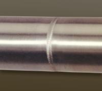 |
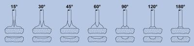
| Figure 7 This weld surface has a pulsed arc finish. |
Arc Pulsing. Arc pulsing involves using the weld power supply to alternate the weld current rapidly from a high (peak current) to a low (background current) value. This creates a seam of overlapping spot welds. This technique reduces the overall heat input to the welding procedure, often improving weld quality and repeatability.
In some cases, materials and weld joints with poor fit-up that are difficult to weld successfully with a nonpulsed arc can be welded with a pulsed arc technique (see Figure 7). The result is improved weld quality and increased output.
In orbital welding, arc pulsing offers another advantage because gravity pulls the weld puddle in different directions as the weld is created around the tube. When the arc is at peak current, the base materials melt and flow together; at the lower background current, the puddle can solidify before becoming liquid at the next peak current pulse.
This diminishes the effect of gravity on the molten weld, minimizes the weld sagging at the 12 and 6 o'clock positions, and reduces the molten weld puddle running/slumping downhill at the 3 and 9 o'clock positions; without pulsing, the molten puddle running/slumping could alter the electrode-to-weld puddle distance. The arc pulsing technique thus becomes more advantageous as the wall thickness increases, resulting in a larger weld puddle.
Arc pulsing involves four welding parameters: peak current, background current, pulse width (duty cycle), and pulse frequency. Parameter combinations vary from company to company and welder to welder. Many welders arrive at the same visual welding result even after having used somewhat different welding parameters.
Peak-to-background current ratios provide a means for the welding current to pulse from one level to another. The industry usually uses ratios varying from 2:1 to 5:1. A good starting point is to use a 3:1 ratio, make the required weld, and test other ratios to see if any benefits can be gained.
The pulse frequency depends on the spot overlap required. A good starting parameter is a 75 percent spot overlap. For orbital welding, the pulses-per-second (PPS) rate for thin-wall tube is often equal to the weld speed in inches per minute (5 IPM = 5 PPS).
The pulse width (the percentage of time spent on the peak current) depends on the heat sensitivity of the material and the available current from the power supply. Higher heat sensitivity may require a lower pulse width percentage on the peak current. Standard pulse widths are often 20 to 50 percent. A good starting parameter is a pulse width of 35 percent.
Free arc pulsation software is available from the Internet that precalculates a variety of arc pulsation parameter for any given amperage or an application. In this fashion, welders can arrive at an acceptable weld program and quickly obtain a variety of alternative arc pulsation options to examine without requiring lengthy calculations or tedious empirical trial and error test welding.
Conclusion
Optimizing the welding process improves weld quality, increases weld speed, and reduces scrap and rework costs. Companies that can achieve this goal can realize lower costs per unit of product, quicker delivery of product, and fewer defects in workmanship. Using orbital welding systems, in conjunction with weld programs, control of input material and shield gas quality, and properly prepared preground electrodes, can be one step toward welding process optimization.
About Pro-Fusion
Copyright © 2003-2015 Pro-Fusion by Elderfield & Hall.
10901 McBride Lane
Knoxville TN 37932
Tel: 865.671.7682
Fax: 865.671.7686
email: sales@pro-fusiononline.com
Privacy Policy, Shipping, Terms & Conditions