 |
|
 |
Determining parameters for GTAW
Starting points for success
By Bernard Mannion and Jack Heinzman III
The gas tungsten arc welding (GTAW) process originally was created in the 1940s to weld magnesium and aluminum alloys for aircraft applications.
It was developed because a welding method was needed that performed better on these materials than did shielded metal arc welding (SMAW). Today, many precision parts are gas tungsten arc welded, including batteries, metal bellows, pacemakers, medical components, and surgical tools (see Figure 1).
Originally, helium was used as the shielding gas, and the process became known as heliarc welding. Argon gas soon became the most widely used shield gas because of its lower cost and smoother arc.
In the GTAW process, an electrical arc is established between a tungsten electrode and the part to be welded. To start the arc, a high voltage is used to break down the insulating gas between the electrode and the part.
Current is then transferred through the electrode to create an electrode arc. The metal to be welded is melted by the intense heat of the arc and fuses together either with or without a filler material.
The arc zone is filled with an inert gas to protect the tungsten electrode and molten material from oxidation and to provide a conducting path for the arc current. Shield gases used are argon, helium, mixtures, of argon and helium, or small percentages of hydrogen mixed with argon. The shield gas usually is chosen according to the material to be welded.
A typical welding system usually consists of the following elements:
- Welding power supply.
- Weld controller.
- Welding torch.
- Tungsten electrode.
Besides the equipment, on of the most important aspects of the GTAW process is the welding parameters used. A weld program consists of a list of welding parameters developed to achieve a specific weld quality and production output.
A change in any parameter will have an effect on the final weld quality, so the welding variables normally are written down or stored in the welding equipment memory.
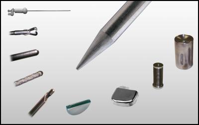 |
| Figure 1 Many precision parts are made using GTAW, including batteries, metal bellows, medical components, and surgical tools. |
For welding in many precision or high-purity applications, a specification may already be written that outlines the recommended welding parameters, including the base material; part diameter(s); weld joint and part fit-up requirements; shield gas type and purity; arc length; and tungsten electrode material, tip geometry, and surface condition.
Some welding equipment suppliers offer a series of precalculated weld programs for a variety of part diameters, materials, and thicknesses. Welders should always follow an equipment supplier's suggested procedures first because the suppliers usually have performed a significant amount of qualifying and troubleshooting work.
Of course, equipment suppliers can not possible have welding procedures for every welding application, This article is intended as a guideline for those GTAW applications in which no specification exists and the engineer responsible for the welding must create the welding setup and derive the welding parameters.
The rules of thumb noted here are general guidelines only and will not apply to every welding application and mix of parameters chosen. Although the welding parameters often are chosen and changed according to the specific needs of the application, some industry standards have been developed as starting points. Experimentation and experience will determine the final weld parameters.
The addition of wire to the process creates many additional parameters. This article focuses on fusion welding only.
Arc Length
The arc length (sometimes called the arc gap) is the distance from the electrode tip to the part to be welded. This setting is dependent on weld current, arc stability, and part concentricity/ovality. The welding engineer's objective is to keep the electrode at a constant distance from the part surface with a sufficient gap to avoid stubbing out.
As a rule of thumb, an arc length of 0.10 inch acts as a base. Half the weld penetration required, expressed in thousandths of an inch, is added to the base measurement to give the arc length for a given amperage.
Thus, if the part material thickness is 0.030 inch, the a good starting arc length would be 0.010 inch + 0.015 inch = 0.025 inch. For a material thickness/ penetration of 0.154 inch, a good starting arc length would be 0.010 inch + 0.072 inch = 0.082 inch.
Weld Speed
The weld speed, which is the speed of travel of the torch over the part or the part under the torch, is dependent on the flow rate of the material to be welded and the material thickness. The objective is to weld as quickly as possible while still yielding a quality output. Weld speed is a predominant factor in defining the production output of a welding system.
Orbital welding equipment weld speeds usually are 4 to 10 inches per minute (IPM), lathe welding speeds may be 5 to 60 IPM, and tube mill welding speeds can vary from 3 IPM to 60 feet per minute (FPM).
As a starting point for parts rotated under a welding torch, the tungsten surface speed should be 10 to 20 IPM, with the faster welding speeds used for thinner-wall materials and the slower speeds used for heavy-wall thicknesses.
Welding Current
The welding current corresponds to the amount of heat applied to the part to effect the weld, and it depends on the material to be welded, material thickness, welding speed, and shield gas. The objective is the achieve defect-free welds with the required penetration.
| Free arc pulsation software, available on the Internet, precalculates a variety of arc pulsation parameters. |
The welder should start by using 1 amp of welding current for every 0.001 inch of material thickness and for each 10-IPM weld speed increment if the material is stainless steel. Thus, for a 0.030 inch material thickness, the average weld current would be 30 amps in the first level with average weld speeds.
To compensate for heat buildup in circular parts during welding, a downslope at the end of the weld or multiple levels of weld current can be used. If the weld current used to initially penetrate the parts were held at the same level for the complete weld, the weld penetration would increase as the weld progressed around the part potentially producing too much penetration.
The number of levels of welding current needed depend greatly on the welding application and the associated welding speed.
Arc Pulsing
Arc pulsing involves using the welding power supply to alternate the weld current rapidly from a high (peak current) to a low (background current) value. This creates a seam of overlapping spot welds. This technique reduces the overall heat input to the base material and also can allow for increases in weld speed.
Arc pulsing brings many benefits to the welding procedure, often improving weld quality and repeatability. In some cases, materials and weld joints with poor fit-up that are difficult to weld successfully with a nonpulsed arc can be welded easily with a pulsed arc technique. The results are improved weld quality and increased output.
Arc pulsing involves four welding parameters: peak current, background current, pulse width (duty cycle), and pulse frequency. Many welders arrive at the same welding result using somewhat different welding parameters. The primary objective is to use the benefits of weld pulsation to improve weld quality and output.
Peak-to-background current ratios. The peak-to-background current ratios basically provide a means for the welding current to pulse form one level to another. Industry usage generally varies from 2:1 to 5:1 ratios. A good starting point is to use a 3:1 ratio, make the required weld, and test other parameters to see if any benefit can be gained.
| Optimizing the welding process in manufacturing will improve weld quality, increase weld speed, and reduce scrap and rework costs. |
Pulse frequency. The pulse frequency depends on the required spot overlap. A good starting parameter is to try to achieve 75 percent spot overlap. The pulse rate for thin-material parts welded at slow speed soften is equal to the weld speed in IPM (for example, 5 IPM = 5 pulses per second).
Pulse width. The pulse width--the percentage of time spent on the peak current--is dependent on the heat sensitivity of the material and the maximum available current from the power supply.
Material with higher heat sensitivity may require a lower pulse width percentage on the peak current. Standard pulse width are often 20 to 50 percent. A good starting point is to set a pulse width of 35 percent.
Free arc pulsation software, available on the Internet, precalculates a variety of arc pulsation parameters for any given amperage of an application. In this fashion, welders can arrive at an acceptable weld program and quickly obtain a variety of alternative arc pulsation options to examine without requiring lengthy calculations or tedious trial-and-error test welding.
Tungsten Welding Electrode
While no one would refute the importance of the ignition device on an automobile air bag or the ripcord of a parachute, the importance of the tungsten electrode for quality welding is of ten overlooked. Whether in manual or automatic welding, this is the area where manufacturing organizations can improve the consistency of their welding output with minor effort.
Safety. The safety issues related to tungsten electrode material are being looked at more closely. Many users of GTAW or plasma welding do not realize that the electrode they use contain thorium, a radioactive element added to the tungsten material to improve arc starting and welding characteristics. The radioactivity is of a low level, but it can be a hazard, especially if radioactive dust is generated when grinding the electrodes to a point.
New tungsten materials now are available, such as lanthanated electrodes, which offer superior arc welding characteristics and are safer because they lack radioactivity.
Electrode Diameter. Larger-diameter electrodes have a longer life but may be more difficult to arc-start at low amperages.
Here is a rule of thumb for electrodes at medium amperages: The electrode diameter multiplied by 1,500 equals the average amperage for acceptable electrode life (with a 20- to 30-degree angle).
Sharper Versus Blunt Electrodes. Sharper electrodes have less arc wander at lower amperages, more consistent arc starting, and a wider arc. More blunt electrodes have a longer life, provide deeper weld penetration for the same amperage levels, and can handle higher amperage levels.
Generally, use 20- to 30-degree angles for up to an average of 90 amps. Higher currents can use larger included angles.
Parameter Development Example
Following is an example of how to determine welding parameters for a 1-inch-diameter part with a 0.030-inch penetration requirement:
- Arc length = 0.010 inch + (1/2 x Penetration required) 0.010 inch + (1/2 x 0.030 inch) = 0.025 inch
- Weld speed = 15-IPM surface speed RPM = IPM/(3.1415 x Diameter) 15/(3.1415 x 1 inch) = 4.77 RPM
- Average welding current levels
- Use 1 amp of welding current per 0.001 inch of material thickness.
- Downslope the weld at weld termination to form a gradual taper with a length approximately two to three times the weld width.
- If heat builds in the part, causing excessive weld pool size or excessive weld penetration at the final stages of the weld, use multiple levels to decrease the weld current gradually as the part is welded.
- Arc pulsation
- Peak current = 0.030-inch material thickness x 1.7 = 51 amps
- Background current = 1/2 of peak current = 17 amps
- Pulse width/duty cycle = 35 percent
- Tungsten electrode diameter and tip geometry
For a 30-amp average welding current, a 0.040-inch or 0.060-inch-diameter electrode ground with a 20-degree included angle and a 0.005-inch tip flat diameter is a good starting point.
Conclusion
Optimizing the welding process is manufacturing will improve weld quality, increase weld speed, and reduce scrap and rework costs.
From this, a company can realize lower costs per unit of product, quicker delivery of product, and fewer defects in workmanship. These can be accomplished through the use of fine-tuned weld programs that offer consistency and repeatability.
About Pro-Fusion
Copyright © 2003-2015 Pro-Fusion by Elderfield & Hall.
10901 McBride Lane
Knoxville TN 37932
Tel: 865.671.7682
Fax: 865.671.7686
email: sales@pro-fusiononline.com
Privacy Policy, Shipping, Terms & Conditions